![]() Objective
Objective
The objective of this lab is to verify Lenz's Law by proving that the magnetic field produced by a current carrying wire is identical to the magnetic field produced by a magnetized object.
![]() Components Used
Components Used
1) Galvanometer
2) Compass
3) Large Solenoid
4) Small Solenoid
5) Brass Bar
6) Iron Bar
7) Power Supply #LVS0003
8) 10MW Resistor
![]() Procedures
Procedures
1) Determine the polarity of the compass.
2) Using
the following Circuit, determine the polarity of the galvanometer:
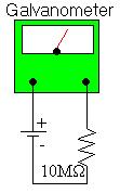
3) Assemble
the following circuit:

4) Set the voltage so about 2A of current flows through the system.
5) Sketch the resulting field.
6) Reverse the polarity and redraw the filed lines.
7) Replace the small solenoid with the large one, and use the compass to determine the field produced by the solenoid.
8) Using the information obtained, and the various "hand" rules to determine the relationship between the current direction and the magnetic field.
9) Use the small solenoid in place of the large one.
10) Power the circuit to 5A.
11) Connect the large solenoid to the galvanometer.
12) Move the small solenoid into the front of the large one and record results.
13) Remove the small solenoid and record results.
14) Repeat steps 12 - 13 except from the rear of the solenoid
15) Repeat steps 12 - 14 using the magnetic rod instead of the small solenoid.
16) Place the small solenoid inside the large one.
17) Rapidly power the solenoid on and off and record results.
18) Reduce the voltage of the power supply so there is little deflection when the power state changes.
19) Insert the iron rod into the center of the small solenoid.
20) Rapidly power the solenoid and record results.
21) Replace the iron rod with the brass rod and repeat step 20.
22) With the power supply off, move the iron rod in and out of the small solenoid and record results.
23) Repeat step 22 using the brass rod.
24) Set the power supply to produce around 3 - 5 A of current.
25) Insert the iron rod halfway into the small solenoid.
26) Power the solenoid and record results.
![]() Lab Data / Results
Lab Data / Results
1) Diagram 1: Schematic 1, Enlarged View:
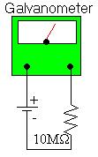
2) Diagram 2: Schematic 2, Enlarged View:

3) Table 1: Polarity:
|
|
Polarity |
|---|---|
|
Compass |
Normal |
|
Galvanometer |
Normal |
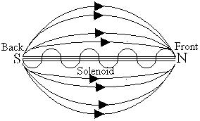
4) Table 2: Field Information from solenoid:
|
Current Direction |
Field |
|---|---|
|
Front |
North |
|
Back |
South |
5) Diagram 3: Field Lines Resulting From Forward Current:
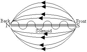
6) Diagram 4: Field Lines Resulting From Reverse Current:
7) Statement 1: Right Hand Rule for Current - Field Direction:
If thumb points in direction of current, field curls around wires in direction of fingers.
8) Table 3: Deflections using the Small Solenoid as a Magnetic Source:
|
|
Insert |
Retract |
|---|---|---|
|
Front: |
Positive |
Negative |
|
Rear: |
Negative |
Positive |
9) Table 4: From front, Deflections observed with Rare Earth Magnet:
|
|
Insert |
Retract |
|---|---|---|
|
North End: |
Positive |
Negative |
|
South End: |
Negative |
Positive |
10) Table 5: Results From Alternation Power Supply States:
|
|
Power On |
Power Off |
|---|---|---|
|
Deflection: |
Positive |
Negative |
11) Table 6: Effects of Iron Rod on deflection:
|
|
Effect |
|---|---|
|
Full: |
Significantly Increased Magnitude |
|
Half: |
Increased Magnitude but only half as much |
12) Table 7: Deflection From Uncharged Rods:
|
|
Iron |
Brass |
|---|---|---|
|
Insert: |
Positive |
No Effect |
|
Retract: |
Negative |
No Effect |
![]() Answer to Lab Questions
Answer to Lab Questions
1) Q: Show the direction of the field at given points on a coil:
A: 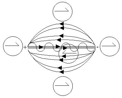
2) Q: Given a galvanometer connected to a coil, and forward current causes a left deflection, when a right deflection is observed, what direction would a south - side magnet in the coil be moving, explain.
A: It would be moving into the coil, a north - side magnet moving into the coil would produce a produce a positive deflection, therefore it would be reversed for a south - side magnet.
3) Q: Show how this lab supports or conflicts with Lenz's Law.
A: This lab supports Lenz's Law because the induced magnetic field opposed the magnetic field that generated it. This is proven consistent with all results.
4) Q: Explain the results involving the iron rod.
A: The iron rod amplified the result because it can help hold a magnetic field, the results were reduced because the rod was not completely involved in the field production (only half) and therefore the effect was reduced by a factor of ½.
5) Q: What is the effect of the iron rod on the field flux, and what proves this?
A: The iron rod increases the flux as observed in the iron rod portion of the results.
6) Q: Explain the difference between the observations between the brass and iron rod.
A: No observations taken (See Conclusions) However, the electron configuration of brass prevents it from easily being affected by magnetism, and therefore. a greater magnitude would have been observed, but not nearly as large as any of the observations involving the iron rod, which is easily magnetizable, and the basis for rare Earth magnets.
7) Q: Describe the source of electricity observed at the galvanometer.
A: The electricity was induced through an electromagnetic conversion: electricity was converted to magnetism and back to electricity following the principle of Faraday's law.
8) Q: Why does a generator become harder to rotate when a load is placed on it?
A: The additional torque is required to overcome the opposite magnetic field that is produced described by Lenz's Law.
![]() Conclusions
Conclusions
From this lab, Lenz's Law can be proven because an equal and opposite magnetic field is induced in a coil that is in a changing magnetic field. Also, this lab probes that a field produced by a current carrying wire is identical to that produced by a Rare Earth magnet. I was unable to fit both the brass rod and the bar magnet into the small coil. To compensate for this problem, the magnetic rod was moved along the outside of the coil and the readings were inverted. However, since the brass rod could not be inserted to observe field amplification, no readings were taken. The brass rod was, however used in the same manner as the bar magnet for residual field detection.
![]() Attachments
Attachments