![]() Objective
Objective
The objective of this lab is to investigate the relationship between current and voltage for several common electrical circuit elements. Then use this data to explain the behavior and effectiveness of resistance.
![]() Components Used
Components Used
1) Variable voltage power supply
2) 300W resistor
3) 500W resistor
4) Multimeter
5) Light bulb
6) GE Diode
![]() Procedures
Procedures
1) Assemble
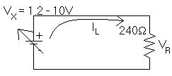
the following circuit:
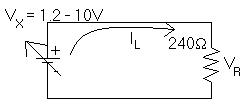
2) Using V=1v - V=10v in 1v increments measure the current through the resistor.
3) Repeat step 2 using the 500W resistor.
4) Repeat step 2 using both resistors in series.
5) Repeat step 2 with both resistors in parallel
6) Replace the resistor with the light bulb and repeat step 2
7) Replace the bulb with the diode in a forward bias configuration.
8) Using voltages of .125V - .5V in .125V increments, find the current through the diode
9) Reverse the diode bias and repeat step 8.
10) Plot all information on graphs.
![]() Lab Data / Results
Lab Data / Results
1) Table 1: Voltage - Current Relationships
|
|
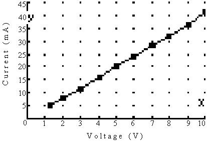
240W |
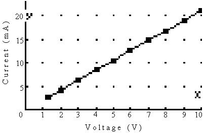
470W |
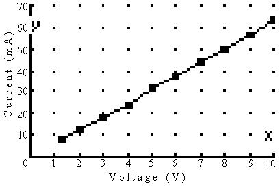
Parallel |
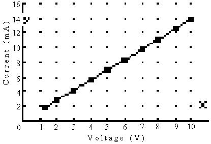
Series |
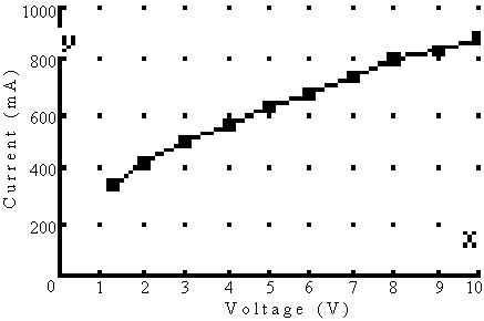
Light |
|---|---|---|---|---|---|
|
1.26V |
4.99mA |
2.62mA |
7.34mA |
1.74mA |
345mA |
|
2V |
7.97mA |
4.19mA |
11.86mA |
2.80mA |
420mA |
|
3V |
11.97mA |
6.28mA |
17.7mA |
4.19mA |
492mA |
|
4V |
15.91mA |
8.36mA |
23.7mA |
5.55mA |
563mA |
|
5V |
20.1mA |
10.52mA |
31.1mA |
6.99mA |
626mA |
|
6V |
23.9mA |
12.5mA |
37.6mA |
8.38mA |
681mA |
|
7V |
28.3mA |
14.8mA |
44.0mA |
9.75mA |
735mA |
|
8V |
31.9mA |
16.8mA |
50.1mA |
11.1mA |
800mA |
|
9V |
36.4mA |
18.9mA |
56.6mA |
12.6mA |
840mA |
|
10V |
41.6mA |
21.1mA |
63.1mA |
13.95mA |
890mA |
2) Diagram 1: Graph of V / I for 240W Resistor
3) Diagram 2: Graph of V / I for 470W Resistor
4) Diagram 3: Graph of V / I for Parallel Resistors
5) Diagram 4: Schematic 1, Enlarged View
6) Diagram 5: Graph of V / I for Series Resistors
7) Diagram 6: Graph of V / I for Light Bulb
![]() Answers to Lab Questions
Answers to Lab Questions
1) Q: Given a curved line and a straight line illustrating the relationship between voltage and current, which one is ohmic?
A: The one with the straight line.
2) Q: Given the lab illustration, what is the resistance of the ohmic material?
A: 1W
3) Q: For the same image, find the resistance at 2V, 4V, and 5V.
A: 2V -> .8W; 4V -> 1.33W; 5V -> 1.67W
4) Q: How does the resistivity of the material increase as the voltage increases?
A: The resistance increases.
5) Q:What is the equivalent resistance of two resistors in series?
A: RT = R1 + R2
6) Q: Is RT greater or less than the individual resistors?
A: Greater
7) Q: If R1 and R2 are both non ohmic, and their equivalent resistances were found independently, then they were put together, would their resistance remain the same, and explain why.
A: No, if they are non ohmic, then there is no linear relationship between the voltage and current, and the voltage would be divided between the two devices.
8) Q: What assumptions are made for ohmic materials?
A: That their resistivity is not dependent on temperature, pressure, or any other physical change.
9) Q: What are the units of aV/T, and are they unitless?
A: There are no units, the result is a scalar number with no properties assigned.
10) Q: What is the value of a/T at room temperature (Rounded Whole)?
A: a @ 55
11) Q: Find the equivalent resistance of a diode as a function of voltage.
A: dI/dV = e^aV/T*a/T
12) Q: What is r at .125V, .25V, and .5V, why are the vlues so different? (Note: no current values were taken so R can not be found)
A: V = .125V : R = 5.13x10⁻⁴W; V = .25V : R = .481W; V = .5V : R = 422KW There is a small current that still flows causing the resistance to change dramatically at low voltages.
13) Q: Does the Current / Voltage data from the diode support the equation I = I0e^aV/T equation, explain.
A: No data was taken that could support or refute this question.
![]() Conclusions
Conclusions
From this lab Ohm's Law can be proven. For ohmic elements, the relationship between current and voltage is linear, and easily predictable. However, there were inaccurate values taken for both of the non-ohmic elements. The light produces inaccurate results because it's current draw was beyond the capabilities of the supply powering it. Also, no readings were made for the diode because there is no available power supply capable of generating safe voltages for the diode (Below 1V). The lowest voltage that can be produced with a conventional power supply (one designed around the LM317 or equivalent) has a minimum voltage of approximately 1.25V. Due to the constant voltage nature of the diode, there was no way of producing a suitable voltage, therefore readings were not taken.
![]() Attachments
Attachments