![]() Objective
Objective
The objective of this lab is to investigate the attenuation of a signal due to multimode fiber-optic cable. Also, to investigate the loss due to the insertion of a connector in the fiber.
![]() Equipment Used
Equipment Used
1) NOYES MLP 4-2 Multimode Light Pack
2) 120M spool of fiber optic cable
![]() Procedures
Procedures
1) Connect the light sources together using the 850nm light source and an ST connector.
2) Without activating the source, measure the power read my the power meter.
3) Remove the fiber from the power meter and measure the ambient light.
4) Place a finger over the input receptacle and measure the light power.
5) Connect the source and meter together using just one piece of fiber and measure the received power.
6) Connect the source and meter together with two pieces of fiber and a barrel SMA connector.
7) Measure the received power.
8) Insert a second connector and a 120M fiber cable and make a new power measurement.
![]() Lab
Data / Results
Lab
Data / Results
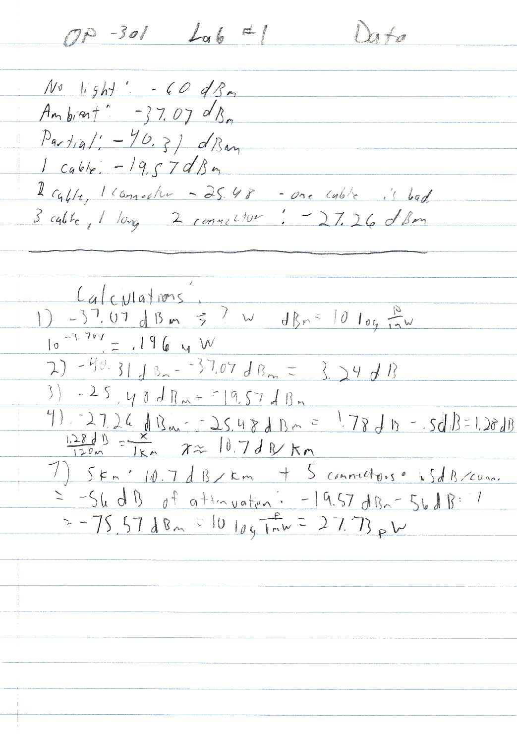
1) Table 1: General lab results
|
Method: |
Relative Power: |
|---|---|
|
Closed circuit |
-60dBm |
|
Ambient light |
-37.07dBm |
|
Covered ambient |
-40.37dBm |
|
Single fiber |
-19.57dBm |
|
2 fibers, 1 connector |
-25.48dBm |
|
2 short fibers, 1 long fiber, 2 connectors |
-27.26dBm |
![]() Answers to Lab Questions
Answers to Lab Questions
1) Q: With no fiber optic cable, how much ambient light enters the power meter?
A: .196mW
2) Q: How much attenuation does a finger provide?
A: Approximately 3.24dB of attenuation, i.e. Half power.
3) Q: Neglecting the loss in the ST connectors, and in the two pieces of fiber cable them selves, what is the loss due to a single SMA type connector?
A: Experimental: 5.91dB of attenuation.
Nominal: .5dB of attenuation
4) Q: Using the nominal value of connector loss, estimate the loss, in dB, of the 120m fiber spool?
A: approximately -10.7dB/Km
5) Q: Assuming an NA of .24, and a lambertain source, what is the expected coupling loss of the connector in dB?
A: .2dB loss
6) Q: Compare the observed loss from Q3 to the loss predicted in Q5, What are possible causes for the discrepancy?
A: Additional loss can be from mismatched area of connectivity, and polarization. Loss can also be attributed from waved that travel outside of the angle of acceptance due to distance between the two butting ends.
7) Q: Given a 5Km optic link between two buildings, with a total of five connectors, using the same source as used in the lab, what would be the optical power received at the far end?
A: 27.73pW
8) Q: Explain why 16dBm - 3dBm @ 13dBm.
A: 13dBm and 3dBm are relative power levels, the difference between then would be an absolute difference: 13dB, and not a relative power level in it's self.
![]() Conclusions
Conclusions
This lab has demonstrated some of the forms of signal loss and attenuation due to multimode fiber optic cable, and it's associated components, to include connectors. One point of difficulty in the lab was predicting the actual connector loss. If I had an estimate of the loss / Km of fiber optic cable, my results would have had more basis. Also, I believe that the loss / Km of cable is also somewhat erratic and is not typical to the losses that I have seen while actually using fiber optic equipment. In situations where there were multiple methods of computing a relevant value, I used the method that would yield the most accurate results, using compensated values wherever possible. Overall, I believe that data I found in this lab is experimentally accurate, but not necessarily accurate.
![]() Attachments
Attachments
