![]() Objective
Objective
The objective is to construct a simple light to frequency converter. Then to use that converter to take samples of operational information.
![]() Equipment Used
Equipment Used
1) Trainer #1055
2) Oscilloscope #1864
3) Multimeter #25004533
4) Various components from the EL - 261 Lab kit
5) Photocell
![]() Procedure
Procedure
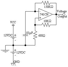
1) Assemble the following circuit:

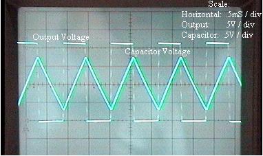
2) Record the waveform at the output.
3) Record the waveform across the capacitor.
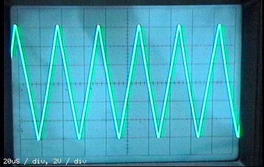
4) Replace the 150KW resistor with the photocell
5) With room light reaching the photocell, record the waveform produced at the output.
6) Calculate the peak voltage and the period
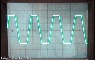
7) Block all light to the photocell and record the resulting waveform at the output.
8) Calculate the peak voltage and period.
![]() Results
Results
1) Diagram 1: Schematic 1 Enlarged View
2) Diagram 2: Waveforms from using the 150KW resistor
3) Diagram 3: Waveforms with photocell using room light conditions
4) Diagram 4: Waveforms with no light at photocell
5) Table 1: Voltages and frequencies of waveforms
|
Lighting |
Voltage: |
Period: |
|---|---|---|
|
Room: |
G6.4V |
38mS |
|
None: |
G11V |
145mS |
![]() Answers to Lab Questions
Answers to Lab Questions
1) Q: What is the frequency obtained in from the 15KW resistor using two methods?
A: Using the oscilloscope: 870Hz; Using the formula: 871Hz; %error: .115%
2) Q: What are the range of frequencies that were observed using the photocell?
A: 6.98KHz - 26.3KHz
3) Q: What is the resistance of the photocell at room light?
A: 4.97KW
4) Q: How can this circuit be altered to be used as a modulator for an incoming signal?
A: 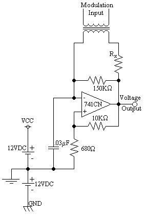
![]() Conclusions
Conclusions
From this lab it is shown that a light to frequency converter can be constructed using a 741 Operation Amplifier and a standard photocell. The accuracy of the results is shown between the two calculations of frequency. The difference being less than 1% (.115%) shows that the readings were exceptionally accurate to the theoretical circumstances.
![]() Attachments
Attachments