![]() Objective
Objective
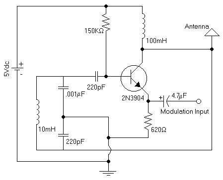
The objective of this lab is to construct a Colpitts oscillator to make an AM transmitter. Then to use that transmitter to record a series of specific measurements.
![]() Equipment Used
Equipment Used
1) Trainer #
2) Dual Trace Oscilloscope #
3) Multimeter #
4) Adjustable Function Generator #
5) Various components from the EL - 261 Lab kit
![]() Procedure
Procedure
1) Assemble the following circuit:
2) Connect the oscilloscope between the antenna and ground.
3) Record the period and amplitude.
4) Using the oscilloscope record, in sync, the collector voltage, base voltage, and the emitter voltage.
5) Apply a 1KHz signal to the modulation input and maximize the amplitude of it so it peaks without distortion.
6) Record the resulting output with respect to the modulating input.
7) Using the Data displayed on the oscilloscope, determine the maximum and minimum voltages, and then calculate the Percent modulation.
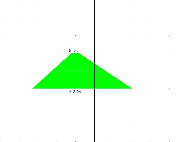
8) Set the oscilloscope up to project the transmitter's trapezoidal pattern, and record it and calculate the percent modulation.
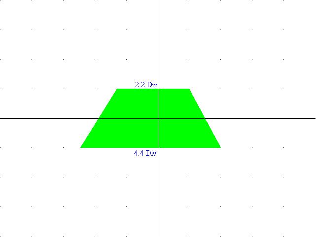
9) Adjust the modulation input so that the transmitter operates at 50% modulation.
10) Record the trapezoidal pattern produced.
11) Set the oscilloscope back to normal and record the resulting wave forms.
12) Using the data on the oscilloscope, record the maximum and minimum voltages.
![]() Results
Results
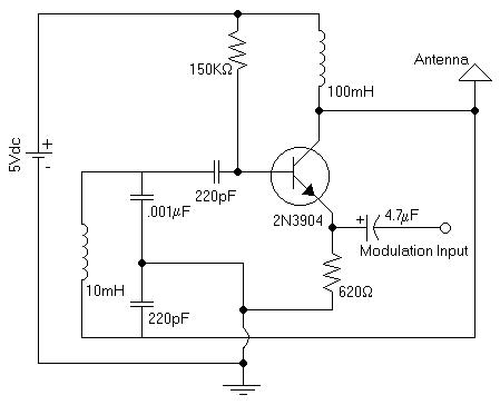
1) Schematic 1: Enlarged view
2) Table 1: Data obtained from Oscillator
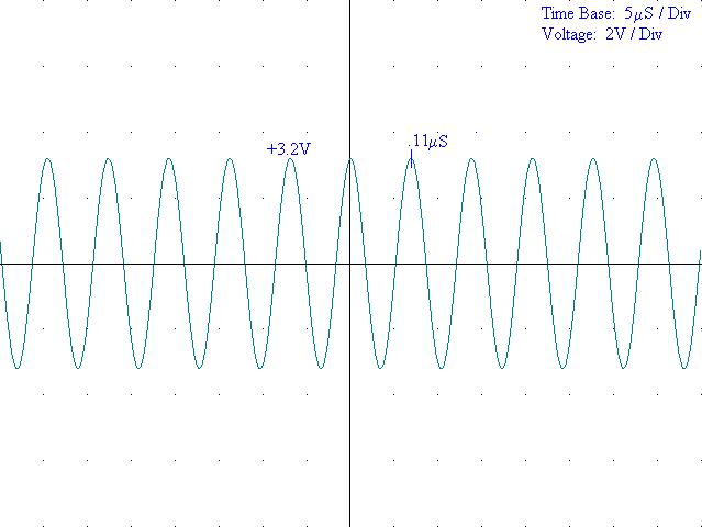
|
Amplitude: |
3.2V |
|---|---|
|
Period: |
.11mS |
|
Frequency: |
90.9KHz |
3) Table 2: Percent Modulation of Transmitter
|
Sinusoidal: |
88.20% |
|---|---|
|
Trapezoidal: |
82.40% |
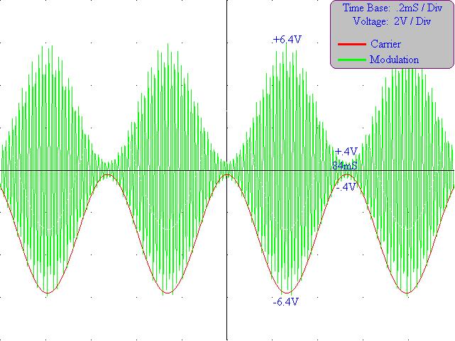
4) Table 3: Maximum and Minimum voltages from Transmitted Wave
|
Minimum: |
.4V |
|---|---|
|
Maximum: |
6.4V |
5) Diagram 2: Oscilloscope results with no modulation: Collector
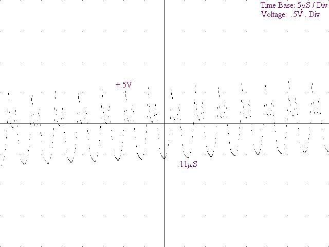
6) Diagram 3: Oscilloscope: Emitter
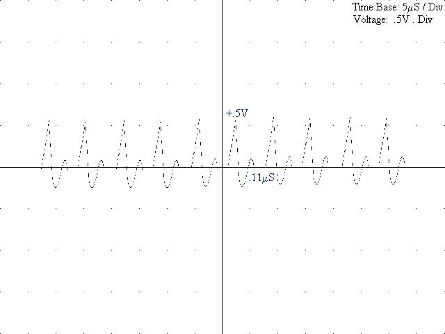
7) Diagram
4: Oscilloscope: Emitter
8) Diagram 5: Output with Incorporated Modulation
9) Diagram
6: Trapezoidal Pattern from Transmitter at Maximum Percent
Modulation
10) Diagram 7: Trapezoidal Pattern at 50% Modulation
11) Diagram
8: Output with 50% Modulation
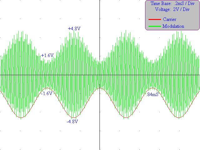
12) Table 4: Voltages from 50% Modulation
|
Minimum: |
1.6V |
|---|---|
|
Maximum: |
4.8V |
![]() Answers to Lab Questions
Answers to Lab Questions
1) Q: What is the carrier frequency of the transmitter?
A: 90.9KHz
2) Q: What is the gain of the Colpitts oscillator, and how does it compare to C4 / C5?
A: 6.4x, It is the similar to the ratio, with experimental error.
3) Q: What is the apparent value of L2?
A: 15.80mH
4) Q: Calculate the following for a load of 500W, using the maximum modulation: Pc, PLSF, PUSF, Pt, PEP, It.
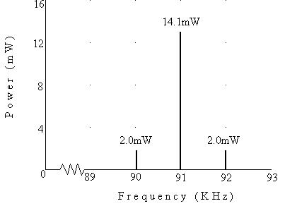
A: Pc = 10.2mW, PLSB = 1.96mW, PUSB = 1.96mW, Pt = 14.12mW, PEP = 14.12mW, It = 2.21mA
5) Q: Show the frequency spectrum of the transmitter at maximum modulation.
A:
6) Q: What are the advantages of using the trapezoid to diagnose the transmitter?
A: The trapezoid not only gives an easy way of determining the modulation index, It is also a way of troubleshooting a malfunctioning transmitter.
![]() Conclusions
Conclusions
From this lab it is shown that a Colpitts oscillator can be used to create a very simple transmitter. That transmitter has the exact same specifications that any other transmitter would, and therefore takes on the same characteristics both in its wave forms and in its trapezoidal analysis.
![]() Attachments
Attachments