![]() Objective
Objective
To design and construct a class A single transistor power amplifier. Then to take readings from the amplifier concerning it's operation.
![]() Equipment Used
Equipment Used
1) Trainer #
2) Oscilloscope #
3) Multimeter #
4) AC function generator #
5) Various components from the EL - 250 lab kit
![]() Procedure
Procedure
A: Circuit Design
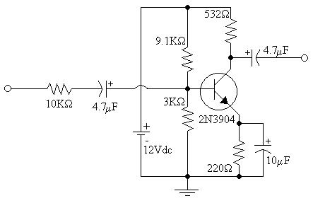
1) Assemble the following circuit:

2) Calculate the values of R1, R2, R3, and R4 so that the following specifications are satisfied:
i: b = 150
ii: ICQ = 6 - 12ma
iii: VRC = 4.8V
iv: VRE = 1.8V
v: IR1 = IR2 = 20IBQ
B: Circuit Construction and Operation
1) Assemble the following circuit:
2) Measure VB, and VC.
3) Apply a 1KHz signal to the input and maximize the input using the oscilloscope as a reference.
4) Measure the voltage at the output, source, and base.
5) Add a 1KW load resistor across the output.
6) Repeat steps 3 and 4.
![]() Data
Data
1) Diagram 1: Schematic 1 - Enlarged view
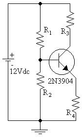
2) Diagram 2: Schematic 2 - Enlarged View

3) Table 1: Resistor values for circuit biasing
|
Resistor: |
R1 |
R2 |
R3 |
R4 |
|---|---|---|---|---|
|
Value: |
9.1KW |
3KW |
220W |
532W |
4) Table 2: DC Voltages at the Base and collector
|
Point: |
Base |
Collector |
Emitter |
|---|---|---|---|
|
Voltage: |
2.84V |
6.93V |
2.11V |
5) Table 3: AC Voltages (No Load)
|
Point: |
Base |
Output |
Source |
|---|---|---|---|
|
Oscilloscope: |
.17V |
4.8V |
1.6V |
|
DMM (RMS): |
147.1mV |
3.675V |
1.023V |
6) Table 4: AC Voltage (1KW Load)
|
Point: |
Base |
Output |
Source |
|---|---|---|---|
|
Oscilloscope: |
.17V |
3.2V |
1.6V |
|
DMM (RMS): |
147.1mV |
2.453V |
1.023V |
![]() Answers to Lab Questions
Answers to Lab Questions
1) Q: What is the theoretical values for the gain and efficiency with this circuit?
A: Av = -196; Ai = -.053; Efficiency = 100%
2) Q: What are the actual values of gain and efficiency for this circuit?
A: Av = -28; Ai = -.688; Efficiency = 57.1%
3) Q: Compare the theoretical and actual values.
A:
|
|
Theoretical: |
Actual: |
% Error: |
|---|---|---|---|
|
Av: |
-196 |
-28 |
85.7% |
|
Ai: |
-0.053 |
-0.688 |
1198% |
|
Efficiency: |
100% |
57.1% |
42.9% |
![]() Conclusions
Conclusions
From this lab a simple power amplifier can be built to conform to a basic set of operational standards. However, I do not know the source of the exceptionally large amount of error between the theoretical values and the real ones. I did, however, find it interesting that wave form that occurs at the emitter of the transistor. The wave form was identical to that of the base, only slightly smaller.
![]() Attachments
Attachments