![]() Objective
Objective
The objective of this lab is to design, and build a simple one transistor, common emitter amplifier. Then to take readings that describe it's operation. Lastly, to use those readings and compare them to theoretical values.
![]() Equipment Used
Equipment Used
1) Trainer #1055
2) Oscilloscope #1864
3) Multimeter #25004533
4) Adjustable Function Generator #1644
5) various components from the EL - 250 Lab kit
![]() Procedure
Procedure
I) Part A: Circuit Design
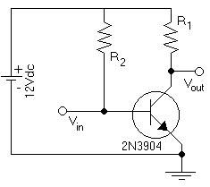
1) Assemble the following circuit:

2) Calculate R1 and R2 using the following conditions:
a) Ic = 10mA
b) Vce = 6V
c) b = 200
II) Part B: Circuit Construction
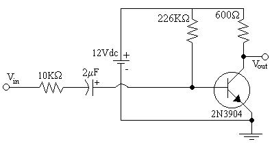
1) Assemble the following circuit:

2) Record the following:
a) Ic
b) Ib
c) Vce
d) Vb
3) Using the function generator, send a 1KHz signal to the input.
4) Connect the oscilloscope to the output and observe the result.
5) Adjust the signal so that it is at it's maximum without distortion.
6) Record the voltage at the collector, emitter, and base.
![]() Data
Data
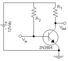
1) Diagram 1: Schematic 1 Enlarged view

2) Table 1: R1 and R2 values
|
R1 |
600W |
|---|---|
|
R2 |
226KW |
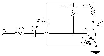
3) Diagram 2: Schematic 2 Enlarged view

4) Table
2: Resulting values from part B
|
Ic |
Ib |
Vce |
Vb |
|---|---|---|---|
|
6.95mA |
50mA |
7.82V |
.73V |
5) Table 3: Resulting voltages as a result of the signal
|
|
Vc |
Vb |
Vs |
|---|---|---|---|
|
rms: |
1.308V |
.1901V |
.2386V |
|
Peak: |
1.7V |
.2V |
.6V |
![]() Answers to Lab Questions
Answers to Lab Questions
1) Q: What is the collector and base current in the amplifier, and what is the dc b?
A: Ic = 6.97mA .2% error, Ib = 49.65mA .7% error, b = 141
2) Q: What is the voltage gain between the resistor and the base?
A: 6.88x
3) Q: What is the source current using the measured voltage at the base and the source?
A: 4.85mA
4) Q: What is the input resistance to the amplifier?
A: 49.2KW
5) Q: Using the value of b experimentally obtained, determine r'e, the voltage gain, and the input resistance to the amplifier.
A: r'e = 3.66W, Av = 164, Zi = 516W
6) Q: Compare using a table, the theoretical values in Q5 to the values discovered in the earlier questions.
A:
|
|
Theoretical |
Actual |
|---|---|---|
|
Av |
-164 |
6.88 |
|
Zi |
516W |
49.2KW |
7) Q: What is r'e using the value of Rc and the measured gain?
A: r'e = 87.2W
8) Q: What causes the difference between the measured and theoretical values?
A: The internal resistance of the oscilloscope.
![]() Conclusions
Conclusions
This lab demonstrates how to build a simple, one transistor, common emitter amplifier. However, I have had difficulty explaining the vast difference between the theoretical values and the calculated ones. The experiment seemed to have been completed with a high level of accuracy; less than one percent difference between the calculated and actual current levels, however the theoretical values portray a large amount of error.
![]() Attachments
Attachments