![]() Objective
Objective
The objective of this lab is to build a synchronous counter using flip - flops and gates. Then to use the counter to demonstrate two different methods of changing it from an up counter to a down counter. Next, to use the counter as a frequency divider. Lastly, to describe the differences between an asynchronous and a synchronous counter.
![]() Equipment Used
Equipment Used
1) Logic trainer #0050516
2) Oscilloscope #
3) 7476 Dual J - K flip - flop x2
4) 7408 Quad 2 input AND gate
![]() Procedure
Procedure
A) Down counter method #1
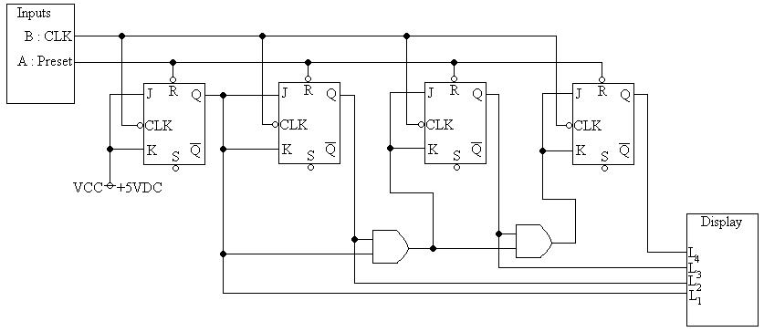
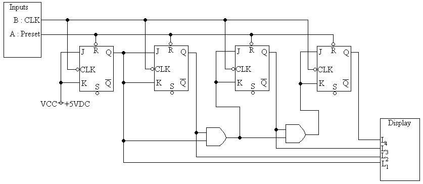
1) Assemble the following circuit:

2) Power the trainer and set the frequency to 1Hz
3) Press switch A to reset the counter and record the resulting truth table for eight clocks
4) Set the trainer to 100KHz
5) Observe each of the outputs on the oscilloscope and record the frequencies
6) Connect the lights to the Q input instead of the Q input
7) Observe the outputs on the oscilloscope and record the frequencies
B) Down counter method #2
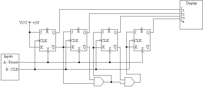
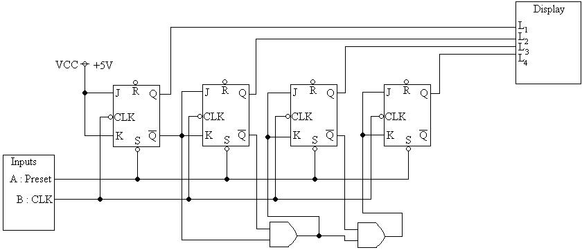
9) Assemble the following circuit:

10) Press and release the A switch
11) Press the clock switch sequentially eight times and record the results
![]() Data & Results
Data & Results
1) Table 1: Truth table from forward counter:
Outputs:
|
Clock count |
Q3 |
Q2 |
Q1 |
Q0 |
|---|---|---|---|---|
|
0 |
0 |
0 |
0 |
0 |
|
1 |
0 |
0 |
0 |
1 |
|
2 |
0 |
0 |
1 |
0 |
|
3 |
0 |
0 |
1 |
1 |
|
4 |
0 |
1 |
0 |
0 |
|
5 |
0 |
1 |
0 |
1 |
|
6 |
0 |
1 |
1 |
0 |
|
7 |
0 |
1 |
1 |
1 |
2) Table 2: Frequencies generated by Q outputs:
Outputs:
|
Logic |
Q3 |
Q2 |
Q1 |
Q0 |
|---|---|---|---|---|
|
Original |
6.3KHz |
13KHz |
25KHz |
50HKz |
|
Inverted |
6.3KHz |
13KHz |
25KHz |
50KHz |
3) Table 3: Truth table from down counter method #2:
Outputs:
|
Clock count |
Q3 |
Q2 |
Q1 |
Q0 |
|---|---|---|---|---|
|
0 |
1 |
1 |
1 |
1 |
|
1 |
1 |
1 |
1 |
0 |
|
2 |
1 |
1 |
0 |
1 |
|
3 |
1 |
1 |
0 |
0 |
|
4 |
1 |
0 |
1 |
1 |
|
5 |
1 |
0 |
1 |
0 |
|
6 |
1 |
0 |
0 |
1 |
|
7 |
1 |
0 |
0 |
0 |
4) Diagram 1: Schematic #1, enlarged view:

5) Diagram 2: Schematic #2, enlarged view:

![]() Answers to Lab Questions
Answers to Lab Questions
1) Q: If a counter sequences from 0000 to 0111, and no further, which flip - flop is defective?
A: The one driving the Q3 output.
2) Q: If the input clock frequency is 64KHz, what is the output frequency at QD?
A: 4KHz / (D + 1)
3) Q: If J and K on the flip - flop controlling the MSB are set to low between the seventh and eighth counts, when the output reads 0111, what will be the output after the clock tick?
A: 0000
4) Q: How many flip - flops are required to count to 100?
A: 27 = 128 > 100; 7.
5) Q: If the Q output on the MSB flip- flop is stuck at 0, how would the problem be diagnosed? _
A: Test the values of Q, J and K, and the clock to ensure that they are correct.
![]() Conclusions
Conclusions
From this lab it is concluded that flip - flop chips can be arranged in multiple ways to construct both up and down counters. Additionally they can be used to construct a 2 - 1 frequency divider. Also the definitions of a synchronous and an asynchronous counter are defined. A Synchronous counter is one that has all clock inputs tied so it does not produce an invalid outcome on the truth table. Whereas an asynchronous counter does not have the tied clock signals.
![]() Attachments
Attachments