![]() Objective
Objective
The objective of this lab is to study the voltage characteristics of a diode to draw it's diode curve.
![]() Equipment Used
Equipment Used
1) ET Trainer
2) Multimeter
3) EL - 200 Lab kit
![]() Procedure
Procedure
1) Measure the forward and reverse resistance of the diode
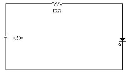
2) Assemble
the following circuit:
3) Measure the voltage across the resistor
4) Measure the current through the circuit
5) Reverse the diode, and change the resistor to 1MW and repeat steps 3 and 4
6) Repeat steps 3 through 5 changing the using the following voltages:
a) 1.0v
b) 2.0v
c) 4.0v
d) 6.0v
e) 8.0v
f) 10v
g) 15v
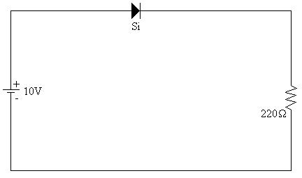
7) Assemble the following circuit

8) Measure the voltage across the resistor
9) Measure the current through the circuit
10) Reverse the diode and repeat steps 8 and 9
![]() Data
Data
A) Table 1: Forward and Reverse Biased Resistances:
|
|
Forward: |
Reverse: |
|---|---|---|
|
Resistance |
18.5KW |
'W |
B) Table 2: Forward Biased Voltages and Currents:
Circuit voltage:
|
Diode: |
.5v |
1.0v |
2.0v |
4.0v |
6.0v |
8.0v |
10v |
15v |
|---|---|---|---|---|---|---|---|---|
|
Voltage |
.50v |
.55v |
.60v |
.60v |
.60v |
.61v |
.61v |
.61v |
|
Current |
.065mA |
.391mA |
1.370mA |
3.423mA |
6.50mA |
7.92mA |
9.80mA |
15.31mA |
B) Table 2: Reversed Biased Voltages and Currents:
Circuit voltage:
|
Diode: |
1.240v |
2.0v |
4.0v |
6.0v |
8.0v |
10v |
15v |
|---|---|---|---|---|---|---|---|
|
Voltage |
1.179v |
1.814v |
2.401v |
2.606v |
2.727v |
2.819v |
2.974v |
|
Current |
0.0000mA |
0.0000mA |
.0001mA |
.0020mA |
.0035mA |
.0055mA |
.0101mA |
*Note: 1.240v in this circuit is the lowest attainable voltage*
C) Table 3: Forward vs. Reverse Bias for Schematic 2:
|
|
Forward Bias |
Reverse Bias |
|---|---|---|
|
Voltage: |
9.31v |
5.05v |
|
Current: |
44.7mA |
24.24mA |
![]() Results
Results
A) Table 1: Forward Biased Results:
Circuit voltage:
|
Diode: |
.5v |
1.0v |
2.0v |
4.0v |
6.0v |
8.0v |
10v |
15v |
|---|---|---|---|---|---|---|---|---|
|
Voltage |
.50v |
.55v |
.60v |
.60v |
.60v |
.61v |
.61v |
.61v |
|
Current |
.065mA |
.391mA |
1.370mA |
3.423mA |
6.50mA |
7.92mA |
9.80mA |
15.31mA |
|
Resistance |
7.69KW |
1.41KW |
438W |
175W |
92W |
77W |
62W |
40W |
B) Table 2: Reversed Biased Results:
Circuit voltage:
|
Diode: |
1.240v |
2.0v |
4.0v |
6.0v |
8.0v |
10v |
15v |
|---|---|---|---|---|---|---|---|
|
Voltage |
1.179v |
1.814v |
2.401v |
2.606v |
2.727v |
2.819v |
2.974v |
|
Current |
0.0000mA |
0.0000mA |
.0001mA |
.0020mA |
.0035mA |
.0055mA |
.0101mA |
|
Resistance |
'W |
'W |
24.01MW |
1.303MW |
779.1KW |
510.9KW |
294.5KW |
*Note: 1.240v in this circuit is the lowest attainable voltage*
C) Diagram 1: Schematic 1 Enlarged view:
D) Diagram 2: Schematic 2 Enlarged View:
E) Diagram 3: Graph of Diode Curve:

![]() Answers
To Lab Questions
Answers
To Lab Questions
1) Q: Plot the Voltage vs. Current for the diode:
A: 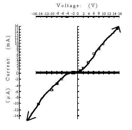
2) Q: Calculate the bulk resistance for the diode:
A: The bulk resistance is:18.5KW.
3) Q: Why do the values of forward resistance and reverse resistance change as the diode's applied voltage change?
A: During forward biased, the diode has a constant voltage drop so it appears to be a variable resistance. During reversed bias, the diode has enough resistance as to let a nearly constant voltage through until it hits breakdown voltage.
4) Q: What approximations were used in this experiment and why?
A: The primary approximation made was that the resistor values were exact. Also, that the multimeters were accurate and did not influence the circuit's operation.
![]() Conclusions
Conclusions
From the data collected, ample information is given to draw a diode curve. The objective was therefore accomplished.
![]() Attachments
Attachments