![]() Objective
Objective
The objective of this lab is to take an “unknown” passive circuit and discover it's order and cutoff frequency. Then, using that information, to create an active filter with the same characteristics.
![]() Components Used
Components Used
1) PC with CircuitMaker® installed.
![]() Procedures
Procedures
1) Simulate the following
circuit:
![]()
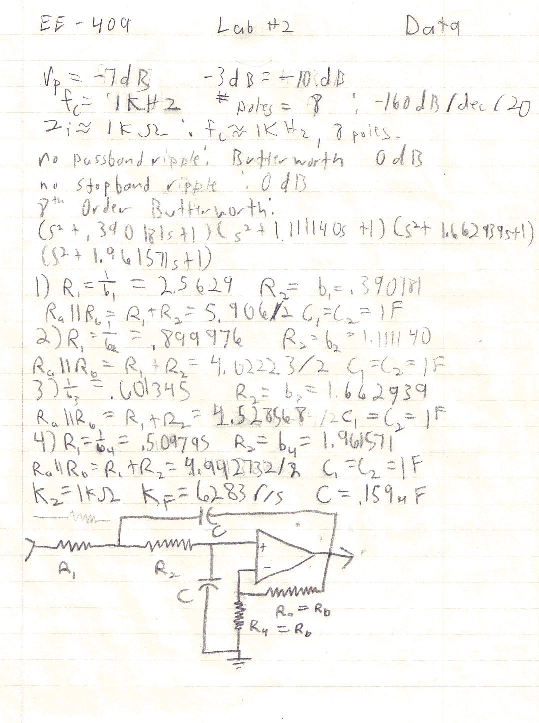
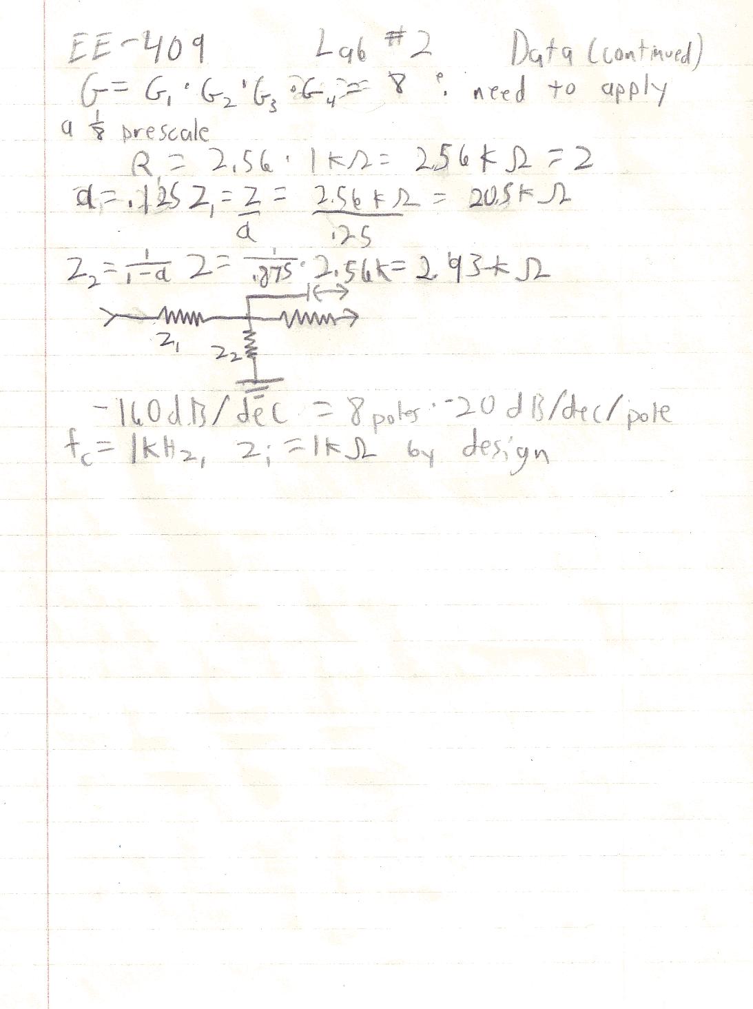
2) Using the information from the simulation, compute the order of the filter and it's cutoff frequency.
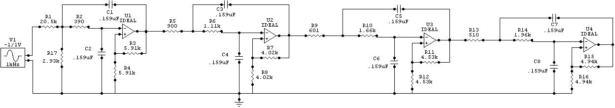
3) Using the data calculated design and simulate an active filter equivalent.
![]() Lab
Data / Results
Lab
Data / Results
1) Table 1: Experimental Filter Data:
|
Input Impedance |
Number of Poles |
Passband Ripple |
Stop band Ripple |
Cutoff Frequency |
|---|---|---|---|---|
|
1KW |
8 |
0dB |
0dB |
1KHz |
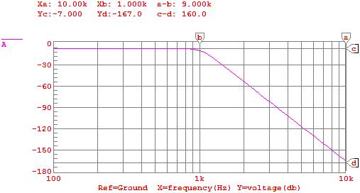
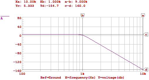
2) Diagram 1: Bode Plot of Network:
3) Diagram 2: Schematic 1 Enlarged View:
![]()
4) Diagram 3: Active Equivalent Schematic
5) Diagram 4: Active Equivalent Frequency Response
6) Table 1: Active Equivalent Data
|
Input Impedance |
Number of Poles |
Passband Ripple |
Stop band Ripple |
Cutoff Frequency |
|---|---|---|---|---|
|
1KW |
8 |
0dB |
0dB |
1KHz |
![]() Conclusions
Conclusions
This lab has demonstrated that, through using simulation, an active filter can be used to replace an unknown passive filter and mirror it's frequency characteristics. Overall, the active filter mirrored the passive filter perfectly. However, even though the active filter was gain compensated, it still had a positive gain. Also, the passive filter had a negative gain that was not compensated for. I believe that the result of the gain was the gain of the system: G(8) = +12dB = 4*(2 = 3dB). However, the Bode plot does not show 12dB of gain reduction, it shows 6dB. I do not know the reason for this. I do believe it to have resulted form the rounding. Looking at the text, the sensitivity of the gain is 2Q. Since most of the time Q > 1 the sensitivity would be high for rounding errors. Compounded with a four stage device, this could add up to 6dB (~ 1.5dB / device).
![]() Attachments
Attachments