![]() Objective
Objective
EE - 401 / E01 Fall 2002
Introductory Communications Theory
Professor: Conner
Submitted By:
Andrew Buettner
Lab #1: Spectral Analysis and Filtering
Table Of Contents
1) Cover Page 1
2) Table of Contents 2
3) Objective 3
4) Components Used 3
5) Procedures 3
6)
Lab Data / Results 3
1) Table 1 3
2) Table 2 3
3) Table 3 4
4) Table 4 4
5) Table 5 4
6) Diagram 1 5
7) Conclusions 5
8) Attachments 5
![]() Objective
Objective
The objective of this lab is to become more familiar with the HP 3585A Spectrum Analyzer. This will be accomplished by making several spectral measurements and then making calculations based on those measurements.
![]() Components Used
Components Used
1) HP 3585A Spectrum Analyzer #1939
2) Function Generator #1512
3) Trainer #1517
4) Oscilloscope #10875
![]() Procedures
Procedures
1) Set the spectrum analyzer to use the 1MW input, have fc of 1MHz and have a frequency span of 500KHz.
2) Use the generator to generate a 1KHz sinewave.
3) Measure the total harmonic distortion over the first five harmonics.
4) Repeat step 3 for a 10KHz signal.
5) Calculate the Fourrier series of both a square wave and a triangle wave
6) Generate a 10KHz square wave and compare the spectrum with the calculated one.
7) Repeat step 6 using a triangle wave.
8) Design a low pass filter with a cutoff frequency of 20KHz.
9) Calculate the spectrum of a 10KHz square wave passed through this filter.
10) Construct the filter and observe the actual spectrum of a 10KHz square wave.
11) Compare the two spectra.
12) Repeat steps 9 - 11 for a triangle wave.
![]() Lab
Data / Results
Lab
Data / Results
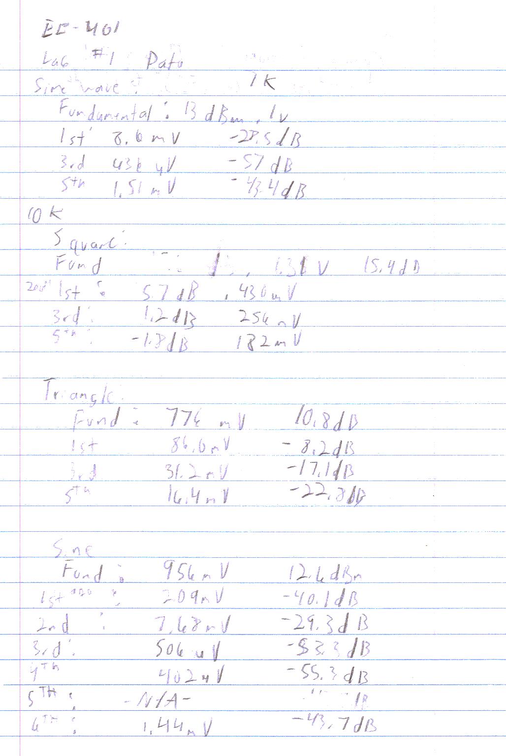
1) Table 1: Harmonic Distortions Observed From a 1KHz Sine Wave:
|
|
Fundamental |
1st Harmonic |
3rd Harmonic |
5th Harmonic |
Total |
|---|---|---|---|---|---|
|
Voltage: |
1V |
8.6mV |
436mV |
1.51mV |
10.54mV |
|
dBm: |
13dBm |
-28.5dBm |
-57.0dBm |
-43.4dBm |
-26.5dBm |
2) Table 2: Harmonic Distortions Observed From a 10KHz Sine Wave:
|
|
Fund. |
1st |
2nd |
3rd |
4th |
5th |
6th |
Total |
|---|---|---|---|---|---|---|---|---|
|
Voltage: |
956mV |
2.09mV |
7.68mV |
506mV |
402mV |
0 |
1.44mV |
12.12mV |
|
dBm: |
12.6dBm |
-40.1dBm |
-29.3dBm |
-53.3dBm |
-55.3dBm |
-'dBm |
-43.7dBm |
-25.3dBm |
3) Table 3: Harmonic Distortions Observed From a 10KHz Square Wave:
|
|
Fund: |
1st |
3rd |
5th |
Total: |
|---|---|---|---|---|---|
|
Expected: |
1.31V |
437mV |
262mV |
187mV |
0 |
|
Observed: |
1.31V |
430mV |
256mV |
182mV |
0 |
|
Difference: |
0 |
7mV |
6mV |
5mV |
18mV |
4) Table 4: Harmonic Distortions Observed From a 10KHz Triangle Wave:
|
|
Fund: |
1st |
3rd |
5th |
Total: |
|---|---|---|---|---|---|
|
Expected: |
776mV |
86.2mV |
31.0mV |
15.8mV |
0 |
|
Observed: |
776mV |
86.0mV |
31.2mV |
16.4mV |
0 |
|
Difference: |
0 |
.2mV |
.2mV |
.6mV |
1mV |
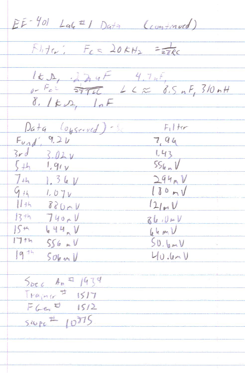
5) Table 5: Harmonics of a 10KHz Square Wave Passed Through a Low - Pass Filter with a Critical Frequency of 20KHz.
|
|
Observed: |
Expected: |
Difference: |
% Error: |
|---|---|---|---|---|
|
Fundamental: |
7.96V |
7.96V |
0 |
0 |
|
1st |
1.43V |
1.05V |
380mV |
36.2% |
|
3rd |
556mV |
449mv |
107mV |
23.8% |
|
5th |
294mV |
249mV |
45mV |
18.1% |
|
7th |
180mV |
158mV |
22mV |
13.9% |
|
9th |
121mV |
110mV |
11mV |
10.0% |
|
11th |
86.0mV |
80.4mV |
5.6mV |
6.97% |
|
13th |
66.0mV |
61.5mV |
4.5mV |
7.32% |
|
15th |
50.6mV |
48.5mV |
2.1mV |
4.33% |
|
17th |
40.6mV |
39.3mV |
1.3mV |
3.31% |
|
Total: |
0 |
0 |
578.5mV |
7.27% |
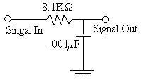
6) Diagram 1: Resistor - Capacitor Network used:

![]() Answers to Lab Questions
Answers to Lab Questions
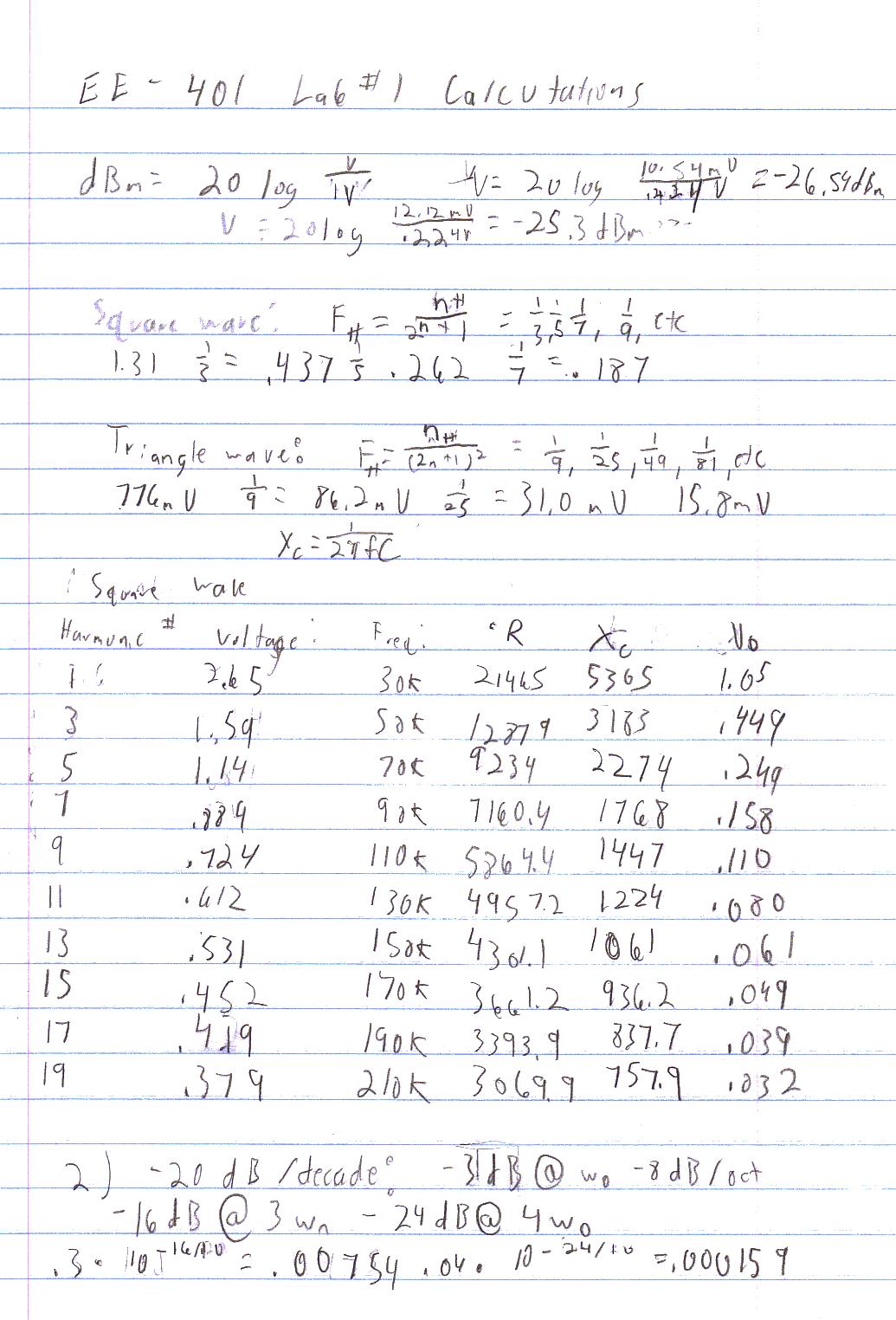
1) Q: What is the total harmonic distortion of the following wave: .5coswot + .3cos3wot + .04cos4wot?
A: .34V
2) Q: If the wave in Q1 was passed through a low pass filter with a cutoff frequency of wo, what would the total harmonic distortion be?
A: fH2 = .00754, fH3 = .000159 THD = .0077
![]() Conclusions
Conclusions
This lab has demonstrated the basic functionality of the HP3585A spectrum analyzer. I am fairly confident in the results. Even though the % error was high on the last phase I believe that it was due to the accuracy of the capacitor. Also, the calculations were not based on the harmonic distortions found in the square wave which could have contributed significantly. Also, I have found that the spectrum it's self has a significant amount of inaccuracy associated with it. Also, I am not sure of the total harmonic distortion calculations are entirely accurate. I believe that there may be errors. My method, which was just summing the individual overtone errors, I do not believe is correct. Other than that, most of the data in this lab should be fairly accurate.
![]() Attachments
Attachments
Original lab handout
Original lab data
Calculations


