![]() Objective
Objective
The objective of this lab is to design an bootstrapped follower BJT amplifier. To make calculations on that circuit and compare them with simulated values. Then compare that circuit to a non bootstrapped version of the same circuit to find the advantages of bootstrapping.
![]() Components Used
Components Used
1) PC with CircuitMaker ® installed.
![]() Procedures
Procedures
1) Using CircuitMaker®,
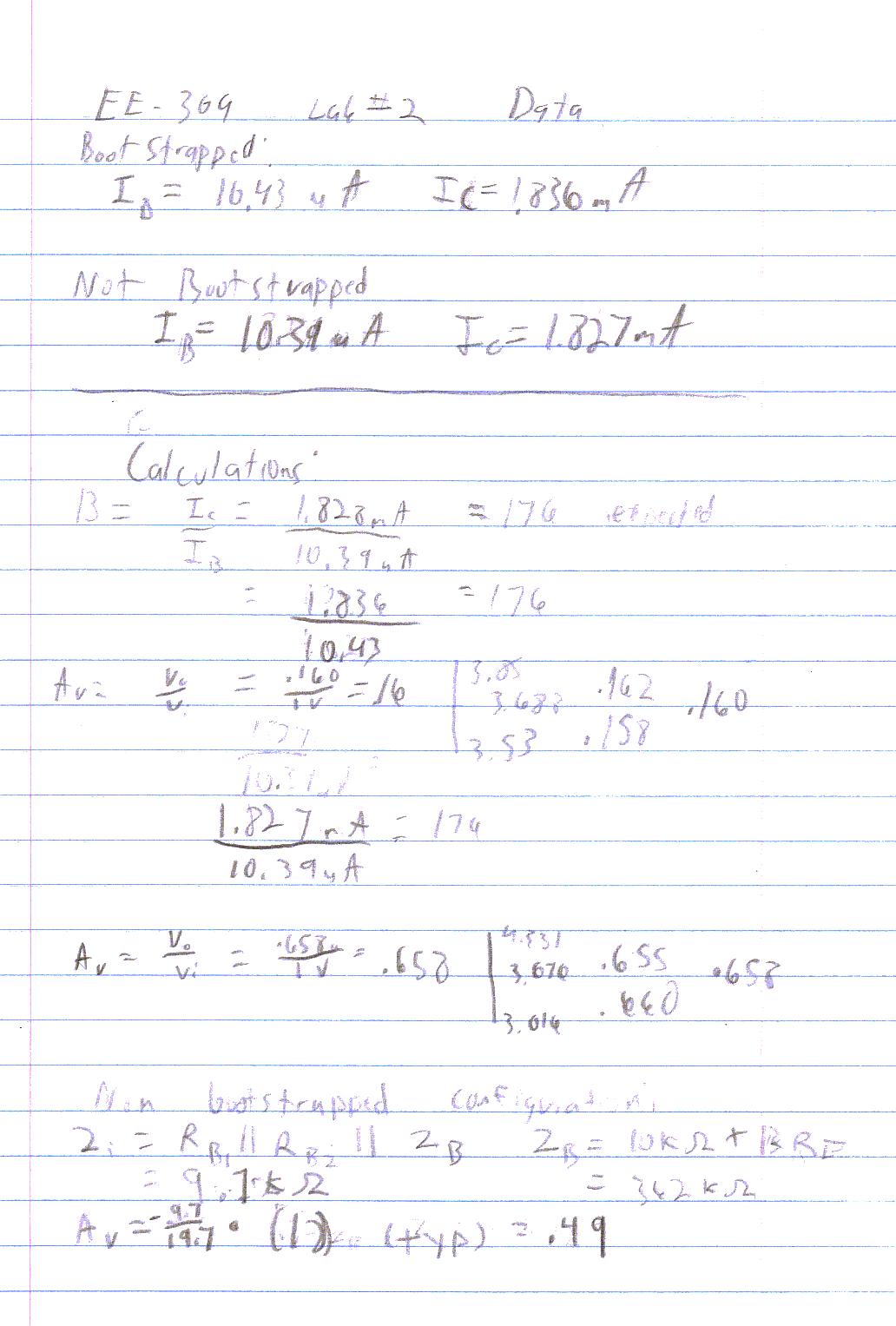
design the following circuit:

2) Simulate the circuit and obtain the DC average values for base and collector current, and the voltage gain.
3) Remove C2, the bootstrapping capacitor and repeat the simulation.
![]() Lab
Data / Results
Lab
Data / Results
1) Diagram 1: Schematic (Enlarged View)
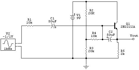
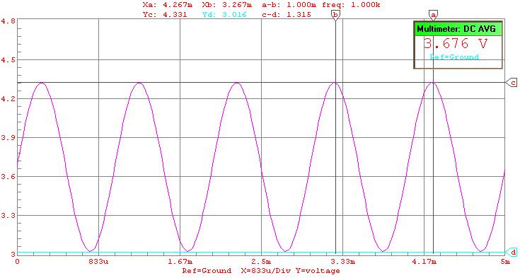
2) Diagram 2: Simulation Data from the Bootstrapped Simulation
3) Table 1: Analytical Data from Bootstrapped Simulation
|
|
IC |
IB |
Gain |
b |
|---|---|---|---|---|
|
Simulated: |
1.836mA |
10.43mA |
0.16 |
176 |
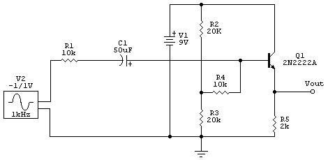
4) Diagram 3: Non Bootstrapped Schematic
5) Diagram 4: Simulation Data from the Non - Bootstrapped Mode
6) Table 2: Analytical Data from Non - Bootstrapped Simulation
|
|
IC |
IB |
Gain |
b |
|---|---|---|---|---|
|
Simulated: |
1.827mA |
10.39mA |
0.66 |
176 |
![]() Answers to Lab Questions
Answers to Lab Questions
1) Q: What is the gm, re and rp of the transistor? Compare those to the CircuitMaker ® values.
A: gm = .172; re = 5.82W; rp = 1024. SPICE model re = 343.0mW
2) Q: Calculate the theoretical the Zi and Av of the bootstrapped circuit. Compare the values to the simulated values.
A: Zi = 5.45KW (No input resistance), 15.45KW (10KW Resistor); Av = .16
3) Q: Calculate the theoretical Zi and Av of the non bootstrapped circuit. Compare the values to the simulated values.
A: Zi = 9.7KW (No input resistance), 19.7KW (10KW Resistor); Av = 1, .49 (Input resistor). Actual Av = .66.
4) Q: Briefly describe the advantages of bootstrapping.
A: Bootstrapping increases the output impedance at the cost of voltage gain for BJT circuits. It does not, however, affect the voltage gain of MESFET based amplifiers.
![]() Conclusions
Conclusions
This lab has demonstrated the a bootstrapped amplifier circuit reduces the input impedance at the cost of forward gain. There were a number of values that I was unable to calculate simply because the circuit examples in the book were pertaining to FETs and not BJTs. However, I believe that the results were good, considering that I did not know what to expect. The Av of the bootstrapped circuit was based on the 10KW resistor being in series with the input. If it hadn't the gain would have been: .45. I am very uncertain of the re PSPICE model, and I do believe that to be errant, especially because of my inexperience with CircuitMaker® .
![]() Attachments
Attachments