Objective
The objective of this lab is to perform routine calculations on a peak rectifier.
Components Used
1) PC with CircuitMaker® installed.
Procedures
1) Using CircuitMaker®,
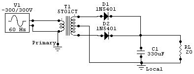
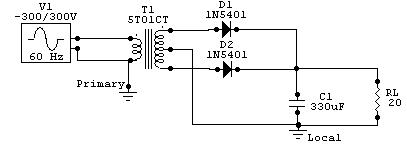
design the following circuit:

2) Using a value of 20W for the load resistor, show the waveform at the output.
3) Repeat step 3 using 200W and 2KW as the load resistor values.
4) What load resistor values produce a reliable output?
5) Add an additional 10W in series with the load resistor and repeat steps 2 - 4.
Lab Data/ Results
1) Diagram 1: Schematic (Enlarged View)

2) Diagram 2: Voltage - Time view using the 20W resistor.

3) Diagram
3: Voltage - Time view using the 200W
resistor.

4) Diagram 4: Voltage - Time view using the 2KW resistor.

5) Diagram 5: Voltage - Time view using the 20W + 10W resistor.

6) Diagram 6: Voltage - Time view using the 200W + 10W resistor.

7) Diagram 7: Voltage - Time view using the 2KW + 10W resistor.

Answers to Lab Questions
1) Q: What is the stability point of the circuit?
A: 2KW
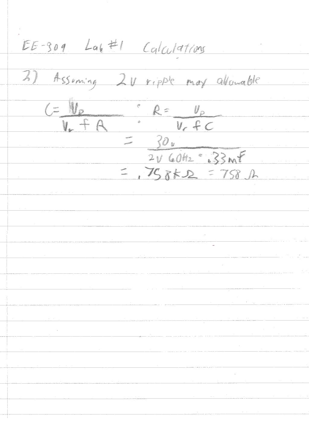
2) Q: According to the formula in the text, what minimum resistance should yield a viable result?
A: 758W
Conclusions
This lab has demonstrated the basic operations of a simple full wave bridge, or peak rectifier. The results were good and were predictable. One note is that the data from the simulations predicts a stable operating point (<2V ripple) at around 1KW, which is expected form the calculations in question 2. I have performed this lab many times in a practical sense when I designed and built power supplies. With a 16W load using a LM317 driven by a power transformer rated at 3A @ 15VACRMS, I was able to achieve less than .1V ripple using 2 2200mF capacitors and a 1000mF on the output.
Attachments
