Capitol College
Spring Semester 2000
Lab Experiment #4
Andy Buettner
Instructor: Dr. Thomas
Due: Friday, April 07 2000
Received: ___________________
Table Of Contents:
Section Page #
Title Page???????????? 1
Table of Contents????????? 2
Objective????????????. 3
Equipment Used?????????.. 3
Equipment used?????????.. 3
Materials used??????????. 3
Procedures???????????... 3
Part 1?????????????... 3
Part 2?????????????... 4
Results?????????????. 4
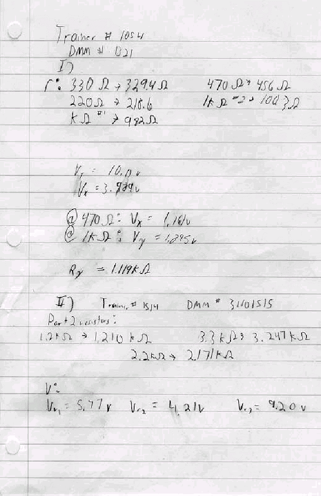
Table 1:????????????... 4
Table 2:????????????... 4
Diagram 1:???????????.. 5
Table 3:????????????... 5
Diagram 2:???????????.. 5
Answers to Lab Questions?????. 6
Conclusions??????????... 10
Attachments??????????... 10
![]() Objective
Objective
The objective of this lab is to study the interactions in more complex circuits in order to prove Thevenin's and Norton's theorems as well as the theorem of superposition. To do this, a circuit is constructed and measurements are made. The results are then compared to values that will be calculated.
![]() Equipment
Used
Equipment
Used
Equipment used:
ET - 3100 Trainer #1054, 1514
Fluke DMM #1321, 31101515
EE - 159 Lab kit
Parts used:
220W Resistor
330W Resistor
470W Resistor
1KW Resistor x2
2.2KW Resistor
3.3KW Resistor
![]() Procedures
Procedures
I) Part 1:
Analyze the circuit below to find the Thevenin's equivalent.
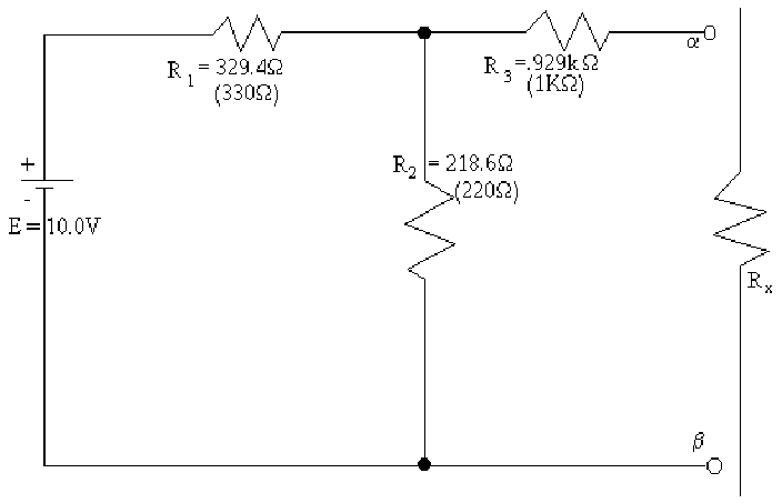
Measure the resistances of the individual resistors.
Assemble the circuit
Power the circuit to 10v
Measure the voltage across the gap.
Place the 1kW resistor across the gap and measure the voltage drop across it
Place a 470 W resistor across the gap and measure the voltage drop across it.
Turn the trainer off and short out the power supply.
Measure the total resistance of the circuit at the gaps.
II) Part 2:
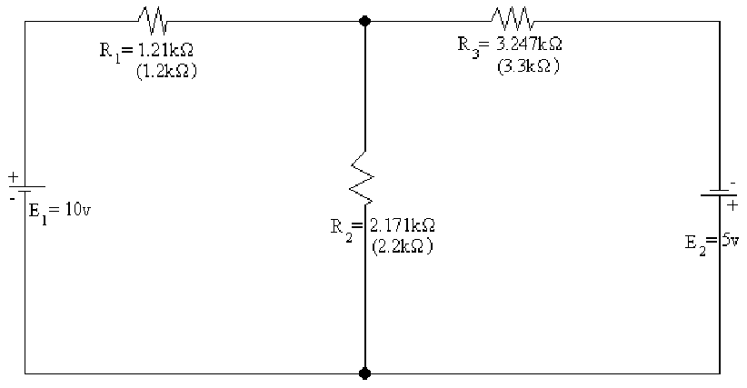
Measure the resistors needed to construct the following circuit.
Construct the following circuit:
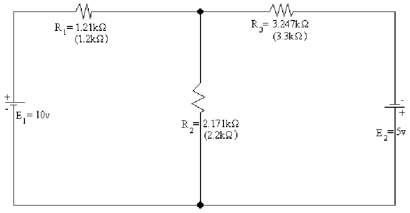
Power the trainer and set the voltages accordingly.
Measure the voltage drop across each resistor.
![]() Results
Results
![]() Table
1: Resistor Values for part 1
Table
1: Resistor Values for part 1
|
Resistor # |
1 |
2 |
3 |
Expected Value |
330W |
220W |
1kW |
|
Actual Value |
329.4W |
218.6W |
.982kW |
![]() Table
2: Voltage values for Rx
Table
2: Voltage values for Rx
|
Resistor # |
none |
1 |
2 |
|
Listed resistance |
|
470W |
1kW |
|
Actual resistance |
|
456W |
1.003kW |
|
Voltage drop |
3.989v |
1.161v |
1.895v |
![]() Diagram
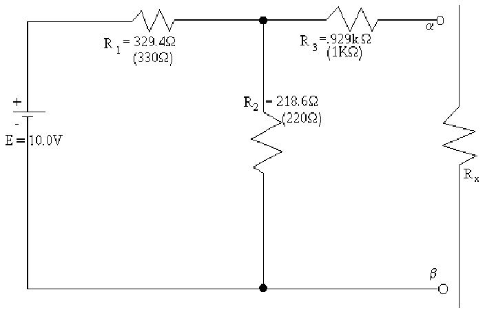
1: Circuit for Part 1 (enlarged view)
Diagram
1: Circuit for Part 1 (enlarged view)
![]() Table
3: Results for Part 2
Table
3: Results for Part 2
|
Resistor # |
1 |
2 |
3 |
Expected Value |
1.2KW |
2.2KW |
3.3KW |
|
Actual Value |
1.210KW |
2.171KW |
3.247KW |
|
Voltage Drop |
5.77v |
4.21v |
9.20v |
![]() Diagram
2: Diagram for Part 2: (Enlarged view)
Diagram
2: Diagram for Part 2: (Enlarged view)
![]() Answers
to Lab Questions
Answers
to Lab Questions
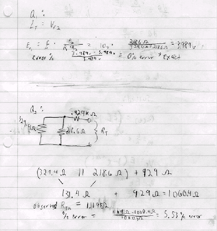
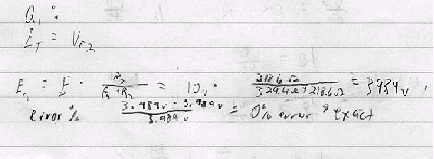
1) Q: What is the Thevenin's equivalent voltage for circuit 1 and how does it compare with the measured voltage?
A: 3.989v: This is an exact value.
Work:
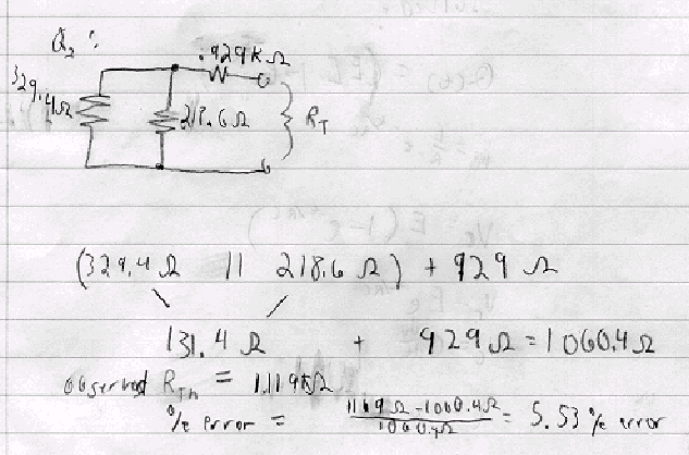
2) Q: What is the Thevenin's equivalent resistance for circuit 1, and how does it compare to the value observed?
A: 1060.4W: With an error of 5.53%
Work:
3) Q: Explain Thevenin's theorem; do the results verify it?
A: Thevenin's theorem states that if there is a complex resistor, and source network that acts on a single resistor, the circuit can be reduced to a circuit containing only one resistor in series with one voltage source. The results verify this because they contain negligible between the values using the theorem and the values that were observed.
Work:
Work shown in problems Q1 and Q2 !
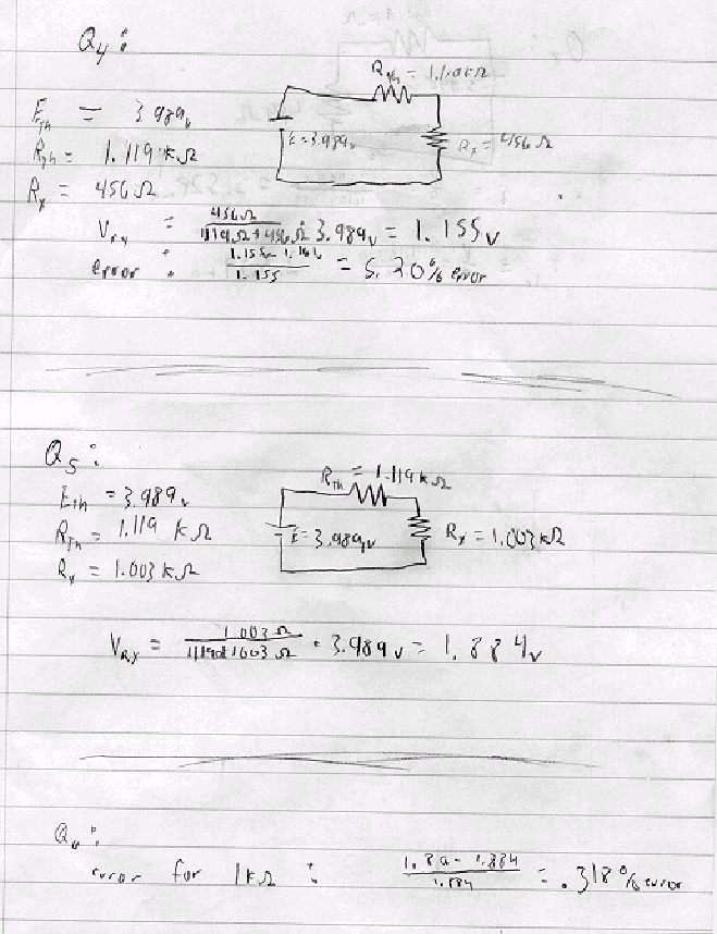
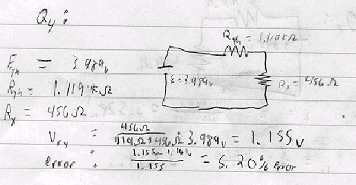
4) Q: What was the voltage across the 470W resistor, and how does it compare with the calculated value?
A: The voltage was 1.161v: With an error of 5.20%
Work:
5) Q: What were the expected and measured resistances across the 1kW resistor?
A1: Observed: 1.895v
A2: Calculated: 1.884v
Work:
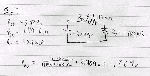
6) Q: Do these results uphold Thevenin's theorem?
A: Yes they do. The errors between the measured and the calculated are very small.
Work:

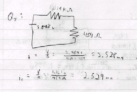
7) Q: What was the current through the 470W resistor?
A1: Calculated: 2.528ma
A2: Observed: 2.529ma
Work:
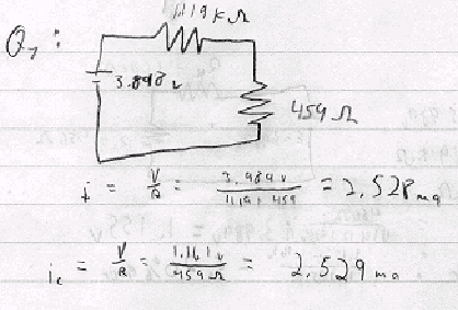
8) Q: Repeat of question 6
A: Repeat of question 6.
Work:
No work is necessary for this problem. !
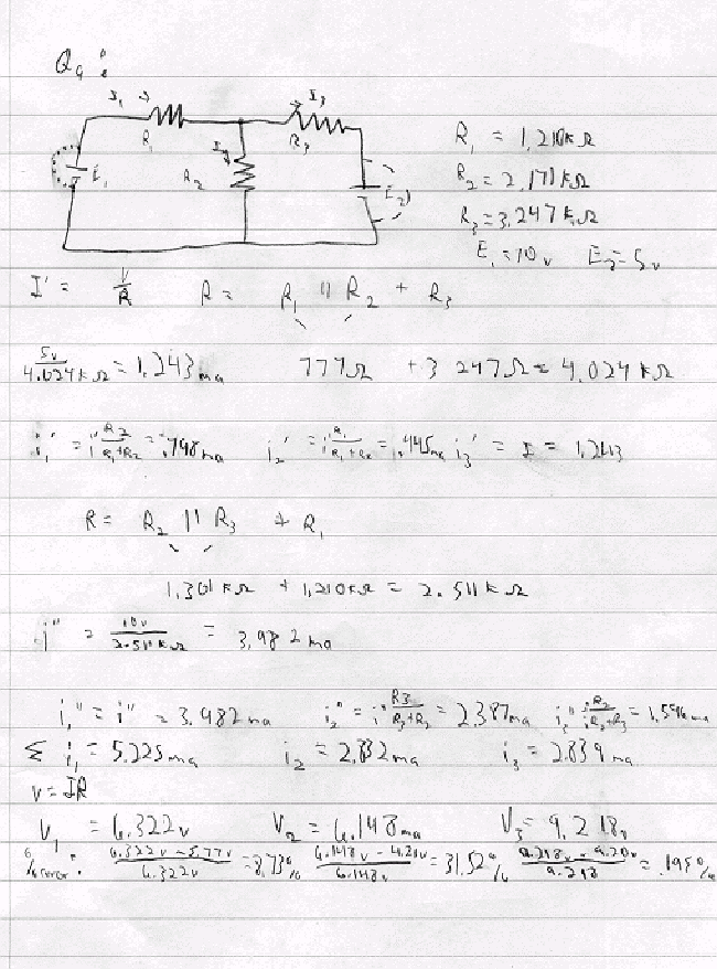
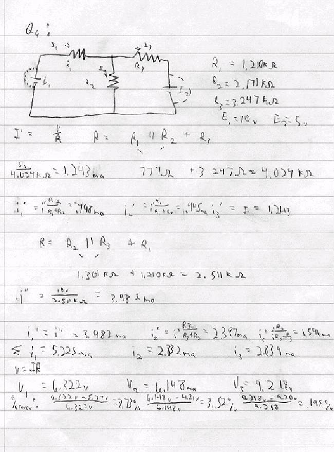
9) Q: What are the individual currents and voltages across the resistors for Circuit 2, and what is the error for the voltages?
A1: Observed: Vr1 = 5.77v Vr2 = 4.21v Vr3 = 9.20v
A2: Calculated: Vr1 =6.322v Vr2 = 6.148v Vr3 = 9.218v
A3: Calculated: Ir1 = 5.225ma Ir2 = 2.832ma Ir3 = 2.839ma
A4: % error: R1 = 8.73% R2 = 31.52% R3 = .195%
Work:
Work shown on next page. !
10) Q: What effect does the internal resistance of the trainer have on the circuit?
A: The effect would is slightly lower observed currents, thus increasing the %error.
Work:
No work is necessary for this problem. !
![]() Conclusions
Conclusions
In conclusion, this lab help affirm that Thevenin's theorem and the theorem of superposition are useful in solving various types of circuits. This is shown by the small error between the calculated values used to solve the various parts of each of the two circuits and the observed results. Only one of the readings was off by a significant figure. I believe that inaccurate equipment as well little compensation for the properties of the trainer were the cause of the error. Finally, this lab proves that these theories can be successfully used to simplify and solve various circuits.
![]() Attachments
Attachments
B) Copies of lab papers
C) Copies of calculations
