Capitol College
Spring Semester 2000
Lab Experiment #3
Andy Buettner
Instructor: Dr. Thomas
Due: March 21st, 2000
Received: ___________________
![]() Objective
Objective
The objective of this lab is to determine the currents in a circuit with multiple sources using mesh analysis. Then, use mesh analysis to analyze a complex circuit. Lastly to compare the results with experimentally determined values.
![]() Equipment
Used
Equipment
Used
Equipment used
ET - 3100 Trainer #1517
Fluke DMM ser. no: 31101554
Lab kit EE - 159
Components used
470 Ohm Resistor
680 Ohm Resistor
330 Ohm Resistor
1K Ohm Resistor
220 Ohm Resistor
![]() Procedures
Procedures
1) Measure and record the individual resistances of each resistor
2) Assemble circuit from Diagram 1
3) Set voltages for both sides of the source
4) Measure voltages across each resistor
1) Measure the individual resistances of the resistors
2) Assemble the circuit in diagram 2
3) Set voltage on Trainer to 10 volts
4) Measure the voltages across each resistor
![]() Results
Results
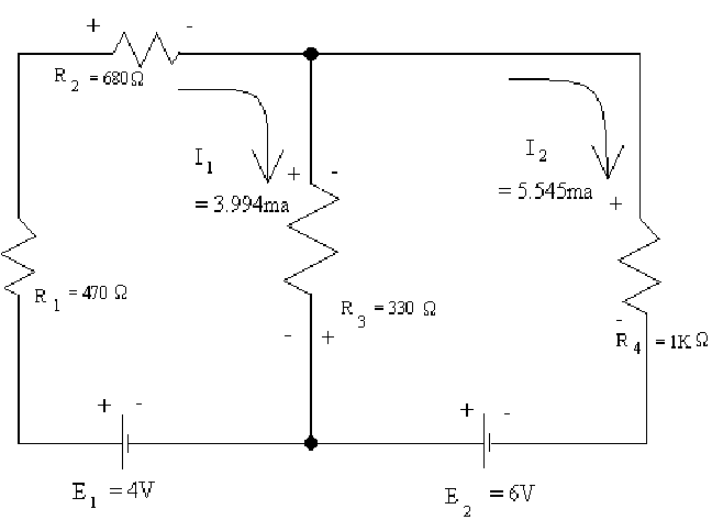
![]() Table
1
Table
1
|
|
R1 |
R2 |
R3 |
R4 |
Measured Resistance |
459 W |
670 W |
329 W |
990 W |
|
Measured Voltage |
1.838V |
2.685V |
.510V |
5.47V |
|
Calculated Current |
4.004ma |
4.007ma |
1.550ma |
5.525ma |
|
Determined Current |
3.994ma |
3.994ma |
1.551ma |
5.545ma |
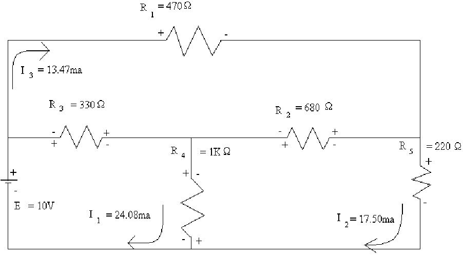
![]() Table
2
Table
2
|
|
R1 |
R2 |
R3 |
R4 |
R5 |
|
Measured Resistance |
459 W |
670 W |
329 W |
990 W |
218 W |
|
Measured Voltage |
6.16V |
2.960V |
3.483V |
6.48V |
3.811V |
|
Calculated Current |
13.42ma |
4.418ma |
10.59ma |
6.545ma |
17.48ma |
|
Determined Current |
13.47ma |
4.03ma |
10.61ma |
6.58ma |
17.50ma |
![]() Diagram
1
Diagram
1
![]() Diagram
2
Diagram
2
![]() Answers
to Lab Questions
Answers
to Lab Questions
Q: Calculate the currents through each resistor using mesh analysis.
A: Answers in tables 1 & 2.
2) Q: Calculate the currents through each resistor using Ohm's law.
A: Answers in Tables 1 & 2.
3) Q: Compare results.
A: The results are nearly identical and in some cases are.
4) Q: Explain how a negative voltage can be made to be positive.
A: Reverse the poles of the volt - meter.
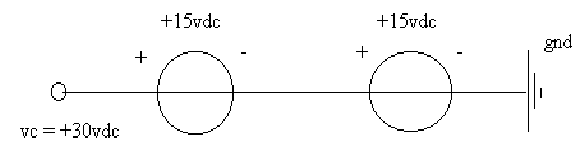
5) Q: The trainer can only produce differences of 15V. How can a difference of 30V be obtained?
A: By using both the positive and negative terminals instead of the ground terminal.
6) Q: What does the DMM read when the battery is low?
A: There is an icon in the top center that shows a battery with an X through it.
![]() Conclusions
Conclusions
In order to complete this lab I used several aids to help me. First, to completely analyze the mesh analysis, I used my equation-solving program to perform the matrix math. Also, I used the found values of the resistors instead of the read ones to complete the mesh analysis. I found it interesting to find out exactly how little error was involved in this exercise.
![]() Attachments
Attachments
Original Handout
Original Data
Calculations