Capitol College
Spring Semester 2000
Lab Experiment #2
Andy Buettner
Instructor: Dr. Thomas
Due: February 18th, 2000
Received: ___________________
![]() Objectives
Objectives
The Objectives of this lab were to study the relationships that exist within series - parallel circuits, and to be able to calculate and measure current through specific points. Additionally, use that knowledge to indirectly calculate the internal resistance of a power source.
![]() Equipment
Used
Equipment
Used
Equipment used
ET - 3100 Trainer ser no: 1614
Fluke DMM ser no: 31101515
Components used
1) EE - 159 lab kit
![]() Procedures
Procedures
Assemble Circuit and record individual resistances
Power the circuit to 5 volts
Measure the voltage across each resistor
Calculate currents through each resistor
Measure the current through the whole circuit
Part 2: Parallel Circuits
Assemble the circuit and measure the resistance of each resistor, and the total resistance of the circuit
Power the circuit to 5 volts and record the currents through each resistor
Calculate the current through each resistor
Part 3: Internal Resistance
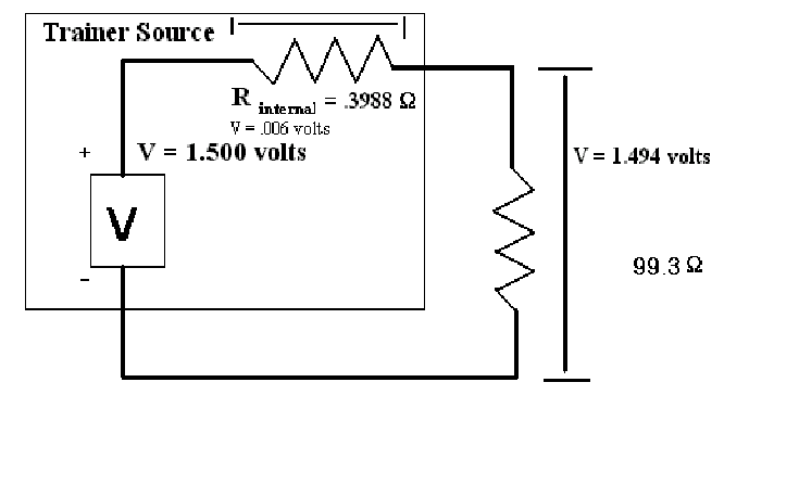
Set the trainer to exactly 1.5v
Connect a 100-ohm resistor between the positive and negative terminals.
Measure the voltage, and calculate the internal voltage drop and resistance.
![]() Schematic
Diagram for part III
Schematic
Diagram for part III

![]() Results
Results
![]() Table
#1: Part 1 master
Table
#1: Part 1 master
|
|
Resistor 1 |
Resistor 2 |
Resistor 3 |
|
Measured Resistance |
151.6W |
329.5W |
459.0W |
|
Measured Voltage |
.804V |
1.754V |
2.443V |
|
Calculated Current |
5.303ma |
5.323ma |
5.322ma |
|
Measured Current |
5.27ma |
5.27ma |
5.27ma |
![]() Table #2: Part 2 master
Table #2: Part 2 master
|
|
Resistor #1 |
Resistor #2 |
Resistor #3 |
|
Measured Resistance |
1.195KW |
2.197KW |
3.248KW |
|
Measured Voltage |
5.00V |
5.00V |
5.00V |
|
Calculated Current |
4.184ma |
2.295ma |
1.539ma |
|
Measured Current |
3.846ma |
2.187ma |
1.488ma |
![]() Answers
to Questions
Answers
to Questions
Q: Compare the calculated currents with the obtained in Table 1: Is the difference expected and why?
A: Yes, the internal resistance of the DMM caused the difference.
Q: Do the same for table 2.
A: Yes, the internal resistance caused a voltage drop across the circuit thus causing a decrease in current.
Q: What was the internal resistance of the Trainer?
A: 3.988W
Q: What is the percent voltage regulation of the Trainer?
A: 0.40%
Q: Is Rtotal equivalent to what is expected?
A: Yes.
Q: Is the total voltage drop in part 1 equal to 5 volts?
A: The total calculated voltage drop is 5.001V; therefore, yes.
Q: Was the Rtotal what was expected?
A: Yes.
Q: Does each current added up equal Itotal?
A: Itotal = 8.018ma: Yes, they are equal.
V2 = 4 volts
V2 = 4.0 volts
V2 = 3.87 volts: The meter creating a significant difference in the total resistance causes the difference.
V2 = 3 volts
![]() Conclusions
Conclusions
My experiences have shown that current is easier and more accurate to derive than any other value in the Ohm's law equation. Additionally, making current measurements adds the most error to results than measuring any other value. Also, calculating the internal resistance of the Trainer had a lot of error in it as the only digit that would have value would be the last digit, which had little significance. A different source, or a better way of determining the voltage drop would be needed.
![]() Attachments
Attachments
Original handouts
Original data
Calculations